Our country’s iron ore resources are rich in reserves and varieties, but there are many lean ores, few rich ores, and fine-spreading granularity. There are few ores that can be directly used. A large amount of ores need to be processed before they can be used.For a long time, there have been more and more difficult beneficiation among the selected ores, the beneficiation ratio has become larger and larger, the process and equipment have become more and more complex, especially the grinding cost has shown an increasing trend.At present, the processing plants generally adopt measures such as more crushing and less grinding, and pre-selection and discarding of waste before grinding, which have achieved remarkable results.
Generally speaking, dry throwing before grinding is more advantageous in the following situations: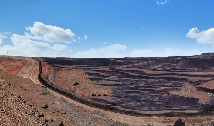
(1) In areas where water resources are scarce, water for mining development cannot be guaranteed, making the feasibility of wet mineral separation not high. Therefore, in these areas, dry pre-selection methods will be considered first.
(2) It is necessary to reduce the volume of tailings slurry and reduce the pressure of the tailings pond. Priority will be given to dry pre-selection and waste disposal.
(3) Dry throwing of large-particle ore is more feasible than water separation.
(4) Dry throwing is usually divided into several stages :
Dry throwing of coarsely crushed products with a maximum particle size of 400~125 mm,Dry polishing of medium-crushed products with a maximum particle size of 100-50 mm,Fine crushing and dry polishing with a maximum particle size of 25~5 mm,As well as the dry polishing of crushed products by high-pressure roller mills, which are currently widely used, the structure of the selected equipment is different.
Dry separation equipment for materials with a maximum particle size of 20 mm or more
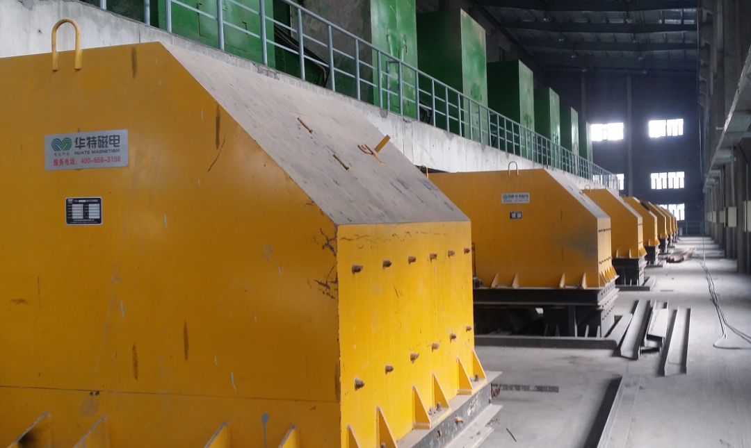
For dry polishing of ore with a maximum particle size of 20 mm or more, the CTDG series permanent magnet dry bulk magnetic separator is currently the most widely used.
Permanent magnet dry bulk magnetic separators are widely used in metallurgical mines and other industries to meet the needs of large, medium and small mines. They are used for the pre-selection of materials with a maximum particle size of not more than 500 mm after crushing in the magnetic separation plant. To restore the geological grade of the waste rock, it can save energy and reduce consumption, and increase the processing capacity of the processing plant;It is used in the stope to recover magnetite ore from waste rock to improve the utilization rate of ore resources; it is used to recover metal iron from steel slag; it is used in garbage disposal to sort useful metals.
Permanent magnet dry bulk magnetic separator mainly uses magnetic force for separation,The ore is evenly fed to the belt and transported to the sorting area on the upper part of the magnetic drum at a constant speed.Under the action of magnetic force, the strong magnetic minerals are adsorbed on the surface of the magnetic drum belt, run to the lower part of the drum and break away from the magnetic field, and fall into the concentrate tank by gravity. The waste rock and weak magnetic ore cannot be attracted by the magnetic force and maintain their inertia. It was thrown flat in front of the partitioning partition and fell into the tailing trough.
From the structural point of view, the permanent magnet dry bulk magnetic separator mainly includes drive motor, elastic pin coupling, drive reducer, cross slide coupling, magnetic drum assembly and magnetic adjustment reducer.
Structural technical points
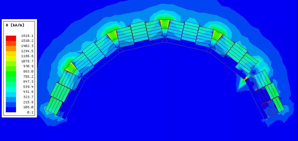
(1) For dry throwing of coarsely crushed products with a maximum particle size of 400-125 mm. Due to the large ore size, the belt conveys a large amount after coarse crushing, and the upper part of the belt conveyor enters the drum sorting area.In order to achieve a reasonable waste disposal effect and reduce the magnetic iron content of the tailings, the magnetic drum at this stage needs to have a larger magnetic penetration depth, so that large particles of ore can be captured.The main technical points of the product structure at this stage:①The larger the roller diameter, the better, usually up to 1 400 mm or 1 500 mm.②The belt width is as wide as possible. The maximum design width of the currently selected belt is 3 000 mm; the belt is as long as possible in the straight section near the head of the drum, so that the material layer entering the sorting area is thinned.③Larger magnetic penetration depth. Take the sorting of ore particles with a maximum particle size of 300-400 mm as an example. Generally, the magnetic field intensity at the distance of 150-200 mm from the drum surface from the drum suction area to the drum surface is greater than 64kA/m, as shown in Figure 1. 1.④The gap between the dividing plate and the drum is greater than 400 mm and is adjustable. ⑤The working speed of the drum is adjustable, and the adjustment of the magnetic declination angle and the adjustment of the distributing device make the sorting index optimal.
Figure 1 Magnetic field cloud map
Table 1 Magnetic field intensity at a certain distance from the magnetic table kA/m
It can be seen from Table 1 that the magnetic field intensity at a distance of 200 mm from the surface of the magnetic system is 81.2 kA/m, and the magnetic field intensity at a distance of 400 mm from the surface of the magnetic system is 21.3 kA/m.
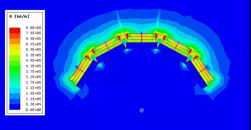
(2) For the dry polishing of medium crushed products with a maximum particle size of 100-50 mm, due to the finer particle size and thinner material layer, design parameters and coarse crushing dry selection can be adjusted appropriately:①The diameter of the drum is usually 1 000, 1 200, 1 400 mm. ②The usual belt width is 1 400, 1 600, 1 800, 2 000 mm; the belt is as long as possible in the straight section near the head of the drum, so that the material layer entering the sorting area is thinned.③Larger magnetic penetration depth, taking the sorting of ore particles with a maximum particle size of 100 mm as an example, usually the magnetic field strength at the distance of 100-50 mm from the drum surface from the drum suction area to the drum surface is greater than 64kA/m, as shown in Figure 2 and Table 2.④The gap between the dividing plate and the drum is greater than 100 mm and is adjustable. ⑤The working speed of the drum is adjustable, and the adjustment of the magnetic declination angle and the adjustment of the distributing device make the sorting index optimal.
Figure 2 Magnetic field cloud map
Table 2 Magnetic field intensity at a certain distance from the magnetic table kA/m
It can be seen from Table 2 that the magnetic field intensity at a distance of 100 mm from the surface of the magnetic system is 105 kA/m, and a magnetic field intensity at a distance of 200 mm from the surface of the magnetic system is 30.1 kA/m.
(3) For dry polishing of finely divided products with a maximum particle size of 25-5 mm, a smaller drum diameter and a smaller magnetic penetration depth can be selected in the design and selection, which will not be discussed here.
Drying equipment for materials with maximum particle size less than 20 mm。
- MCTF series pulsating dry magnetic separator
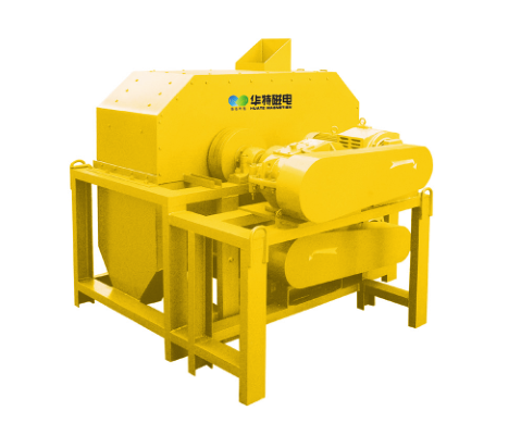
MCTF series pulsating dry magnetic separator is a medium field strength magnetic separation equipment. It is suitable for soft ores such as sandstone ore, sand ore, river sand, sea sand, etc. or crushed powdery lean ore with a particle size of 20~0 mm. Concentration of magnetic minerals and dry pre-selection of finely crushed magnetite products.
1.2 Working principle
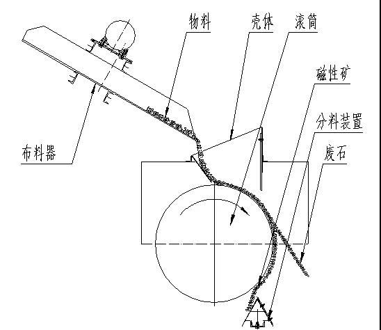
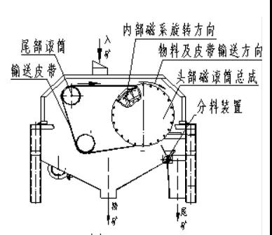
The working principle of MCTF series pulsating dry magnetic separator is shown in Figure 3.
Figure 3 Schematic diagram of the working principle of MCTF type pulsating dry magnetic separator
Using the principle that magnetic materials can be attracted by permanent magnets, a semicircular magnetic system with a larger magnetic field is set inside the drum through which the materials flow.When the material flows through the magnetic field, the magnetic mineral particles are captured by the strong magnetic force and adsorbed on the surface of the semi-circular magnetic system.When the magnetic mineral particles are brought to the lower non-magnetic area by the rotating drum, they fall to the concentrate outlet and are discharged under the action of gravity.Non-magnetic ore or ore with lower iron grade can freely flow through the magnetic field to the tailings outlet under the action of gravity and centrifugal force.
From the structural point of view, the MCTF-type pulsating dry magnetic separator mainly includes a magnetic system adjustment device, a drum assembly, an upper shell, a dust cover, a frame, a transmission device, and a distribution device.
Structural technical points
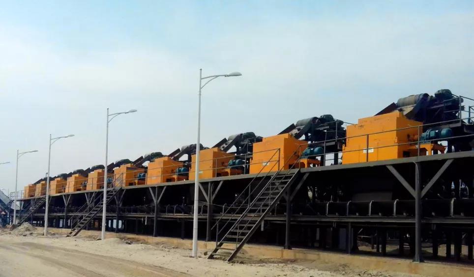
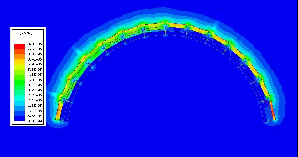
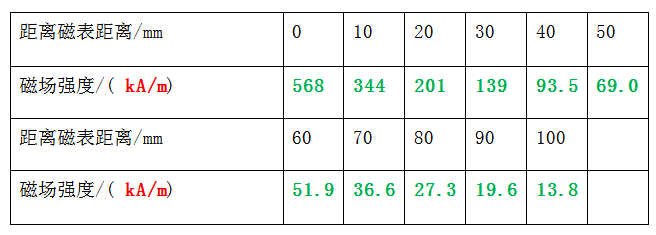
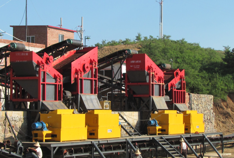
The main technical points of the structure include: ①The commonly used roller diameters are 800, 1,000, and 1 200 mm; the design follows the principle that the finer the particle size corresponds to the smaller diameter, and the coarser the particle size corresponds to the larger the diameter of the drum.②The length of the drum is usually controlled within 3,000 mm. If the drum is too long, the cloth will not be uniform in the length direction, which will affect the sorting effect.③As the particle size of the material becomes finer, the magnetic penetration depth of the drum becomes shallower; the number of magnetic poles increases, which is conducive to the multiple turnover of the material and realizes the separation of the refined tailings of the material; when the thickness of the material layer is 30 mm, the distance from the drum surface is 30 The magnetic field intensity at mm is 64kA/m, see Figure 4 and Table 3.④The gap between the dividing plate and the drum is greater than 20 mm and is adjustable. ⑤In order to ensure uniform distribution in the length of the drum, the equipment should be equipped with auxiliary equipment such as chute, vibrating feeder, spiral distributor or star distributor.⑥For stable sorting index, it can be equipped with a feeding metering device to realize quantitative feeding. ⑦The working speed of the drum is adjustable, and the adjustment of the magnetic declination angle and the adjustment of the material distribution device make the sorting index optimal. The application site of MCTF pulsating dry magnetic separator with vibrating feeder is shown in Figure 5.
Figure 4 Magnetic field cloud map
Table 3 Magnetic field intensity at a certain distance from the magnetic table kA/m
It can be seen from Table 3 that the magnetic field intensity at a distance of 30 mm from the surface of the magnetic system is 139kA/m, and the magnetic field intensity at a distance of 100 mm from the surface of the magnetic system is 13.8kA/m.
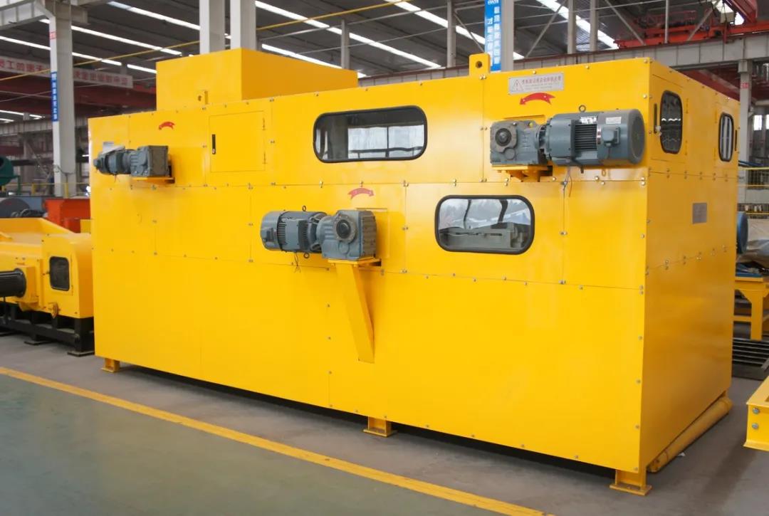
Figure 5 Application site of MCTF pulsating dry magnetic separator with vibrating feeder
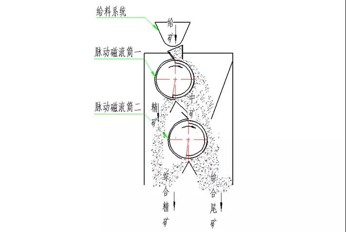
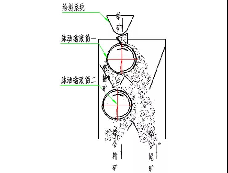
2.MCTF series double drum pulsating dry magnetic separator
2.1 The working principle of a rough sweep
The equipment enters the ore through the feeding device. After the ore is sorted by the first drum, part of the concentrate is first taken out. The tailings of the first drum enter the second drum for sweeping, and the sweeping concentrate and the first concentrate are mixed to become the final concentrate. , The tailings that are scavenged are the final tailings. The working principle of one rough sweep is shown in Figure 6.
2.2 The working principle of one rough and one fine
The equipment enters the ore through the feeding device. After the ore is sorted by the first drum, part of the tailings is first thrown away. The concentrate of the first drum enters the second drum for selection, and the second drum sorting concentrate is the final concentrate. The second dressing tailings are merged into the final tailings. The working principle of one rough and one fine is shown in Figure 7.
Fig. 7 Illustration of working principle of rough and fine
Structural technical points
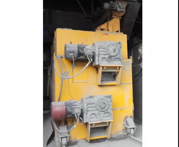
Technical points of 2MCTF series double drum pulsating dry magnetic separator:①The basic design principle is the same as the MCTF series pulsating dry magnetic separator. ②The magnetic field intensity of the second tube is greater than that of the first tube when the first is rough and the first sweep; the magnetic field intensity of the second tube is lower than the first tube when the first is coarse and the other fine. The application site of the 2MCTF double drum pulsating dry magnetic separator equipped with a star-shaped feeding device and an automatic metering device is shown in Figure 8.
Figure 8 Application site of 2MCTF double drum pulsating dry magnetic separator equipped with star-shaped feeding device and automatic metering device。
3.3MCTF series three-drum pulsating dry magnetic separator
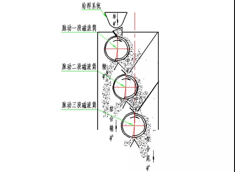
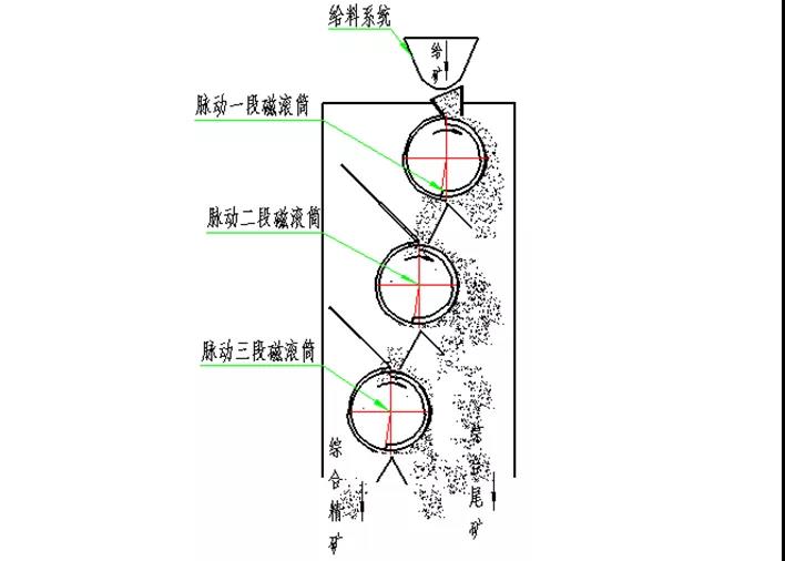
3.1 Working principle of one rough and two sweeps
The equipment enters the ore through the feeding device, the ore is sorted by the first drum, and part of the concentrate is first taken out. The tailings of the first drum enter the second drum sweeping, the second drum tailings enter the third drum sweeping, and the third drum tailings For the final tailings, the concentrates of the first, second, and third barrels are merged into the final concentrate. The working principle of one rough and two sweeps is shown in Figure 9.
Figure 9 Schematic diagram of the working principle of one rough and two sweeps
The equipment enters the ore through the feeding device. After the ore is sorted by the first drum, the concentrate enters the second drum for further separation, the second drum concentrate enters the third drum sorting, and the third drum concentrate is the final concentrate. The tailings of the second and third drums are merged into the final tailings. The working principle of one rough and two fines is shown in Figure 10.
Figure 10 Schematic diagram of the working principle of one rough and two fine
Structural technical points
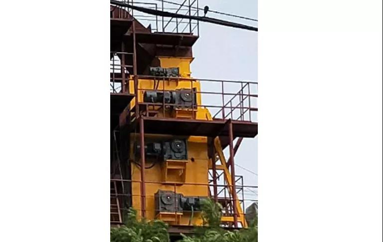
Technical points of 3MCTF series three-roller pulsating dry magnetic separator: ①The basic design principle is the same as MCTF series pulsating dry magnetic separator. ②The magnetic field intensity of the second tube and the third tube increases in order of one rough and two sweeps; the magnetic field intensity of the second tube and the third tube decreases in order of one rough and two fine. The application site of 3MCTF series three-drum pulsating dry magnetic separator is shown in Figure 11.
Figure 11 Application site of 3MCTF three-drum pulsating dry magnetic separator
4. CTGY series permanent magnetic rotating magnetic field dry magnetic separator
The working principle of CTGY series permanent magnet rotating magnetic field dry magnetic separator is shown in Figure 12.
Figure 12 The working principle of CTGY series permanent magnetic rotating magnetic field dry magnetic separator.
CTGY series permanent magnet rotating magnetic field pre-selector [3] adopts composite magnetic system, through two sets of mechanical transmission mechanism, realizes the reverse rotation of the magnetic system and the drum, produces rapid polarity change, so that the magnetic material can be separated in a long distance. The medium is more completely separated from non-magnetic and weak magnetic materials.
The material falls on the conveyor belt through the feeding port above the feeding device, and the conveyor belt moves under the action of the separating motor, and the rotating magnetic field rotates in the opposite direction under the action of the motor (relative to the belt).After the material is brought to the magnetic field by the conveying belt, the magnetic material is tightly adsorbed on the belt and subjected to strong magnetic stirring action, resulting in turning and jumping, and “squeezing” the non-magnetic material to the upper layer of the material under the action of gravity and centrifugal force. , Quickly enter the non-magnetic box. The magnetic substance is adsorbed to the belt and continues to run under the drum. When it leaves the magnetic field, it enters the magnetic box under the action of gravity and centrifugal force to realize the effective separation of the magnetic substance and the non-magnetic substance.
Structural technical points
The basic structure of CTGY series permanent magnetic rotating magnetic field dry magnetic separator includes frame, feed box, drum, tailings box, concentrate box, magnetic transmission system, drum transmission system, etc.
Technical points of CTGY series permanent magnetic rotating magnetic field dry magnetic separator:①The magnetic system design adopts concentric rotating magnetic system, the magnetic wrap angle is 360°, the circumferential direction is alternately arranged according to the NSN polarity, and the unique magnetic concentration technology is used. NdFeB wedge magnetic block groups are added between the magnetic groups to make the drum The strength is increased by more than 1.5 times, and the number of magnetic poles is doubled at the same time, which increases the number of tumbling during the material sorting process, and can effectively throw away weak magnetic substances and mixed gangues in minerals.The high-performance, high-coercivity, high-temperature and high-temperature-resistant rare earth neodymium iron boron is used as the magnetic source, and the magnetic pole plates are made of high-permeability material DT3 electrical pure iron, which greatly improves the permeability. The core shaft minimizes the magnetic field loss, and the magnetic field strength on the surface of the magnetic cylinder is effectively improved, which improves the recovery rate of ferromagnetic materials.②The drum magnetic system is frequency-converted and speed-regulated separately. Two geared motors are selected to control the speed of the drum and the rotation of the magnetic system respectively, and the two geared motors are respectively controlled by two inverters. The speed of the motor can be changed by adjusting the frequency of the motor at will , By changing the rotation speed of the drum and the rotation speed of the magnetic system, the number of tumbling of the mineral particles is controlled.③The permanent magnet roller barrel is made of glass fiber reinforced plastic made of epoxy resin, which avoids the heating of the roller and increases the motor power due to the effect of eddy current.
5. CXFG Series Suspended Magnetic Separator
5.1 Main structure and working principle
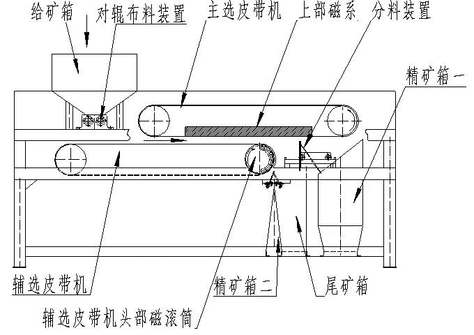
The CXFG series suspension magnetic separator is mainly composed of a feeding box, a counter-roller distributing device, a main belt conveyor, an auxiliary belt conveyor, a magnetic system, a distribution device, a stopper device, a concentrate box, a tailings box, a frame and a transmission System composition.
The sorting principle of the CXFG series suspension magnetic separator is to use the roller mechanism to evenly feed the material to the surface of the conveyor belt of the auxiliary belt conveyor. The magnetic system on the main belt conveyor is located on the upper part of the material to separate the strong magnetic minerals. It is picked up and sent to the concentrate box. When the weakly magnetic materials pass through the head of the auxiliary belt conveyor, they are absorbed on the surface of the drum by the magnetic system in the drum, and fall into the concentrate box after being separated from the magnetic field as the drum rotates. Non-magnetic minerals are thrown into the tailings box under the action of inertial force of motion and gravity, so as to achieve the purpose of sorting. The working principle of CXFG series suspension magnetic separator is shown in Figure 13.
Figure 13 The working principle of CXFG series suspension magnetic separator
Structural technical points
Technical points of CXFG series suspension magnetic separator:①Using counter-roller type cloth can not only ensure the uniformity of the processing capacity and material layer, but also can intercept and assist the crushing of large-grain ore. There is a certain gap between the two pairs of rollers. A pair of intermeshing gears are driven to rotate synchronously and reversely through a constant frequency reduction motor. The user can adjust the speed of the pair of rollers according to the output to adjust the amount of ore.②The main separation belt conveyor adopts an open planar magnetic system, with multiple magnetic poles alternately arranged. The planar magnetic system has a long separation area and a long time of magnetization, which creates more adsorption opportunities for magnetic ore. And because the magnetic system is on the upper part of the ore, the magnetic iron In the sorting area, it is in a suspended and loose state, the monomer is adsorbed, there is no inclusion phenomenon, and the efficiency of improving the grade is much higher than that of the curved magnetic system.The magnetic minerals move along the magnetic poles and pass through the plane magnetic system. The magnetic minerals are automatically turned over many times. The frequency of turning is large and the time is long, which is beneficial to improve the grade of magnetic minerals.In the planar magnetic system, the design has a clever and reasonable magnetic difference, and the minerals are always under the action of multi-polar magnetic poles, which effectively separates the gangue and non-magnetic minerals, thereby obtaining full recovery, improving the concentrate grade and reducing Tail runner.③The auxiliary belt conveyor is mainly used to transport minerals, and the head adopts the structure of magnetic drum to separate small particles. The roller adopts a groove structure to prevent belt deviation.
The above-mentioned series of products produced by Shandong Huate Magnetoelectric Technology Co., Ltd. are suitable for the separation of minerals of different particle sizes. They have their own focus on product structure design to meet the requirements of different sorting indexes, and they have been successfully applied. In many mining enterprises, it has played a positive role in saving energy and reducing consumption and improving efficiency.
Mining enterprises should select magnetic separation equipment suitable for their own business conditions according to the nature of the ore and technological conditions to improve production efficiency.
Equipment manufacturers should continuously improve and perfect the performance of their products according to the production requirements of mining enterprises, solve some problems in actual use, produce products more suitable for industrial applications, and promote the technological development of magnetic separation equipment.
Post time: Mar-17-2021

