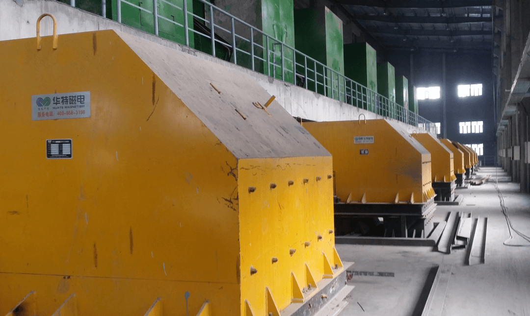
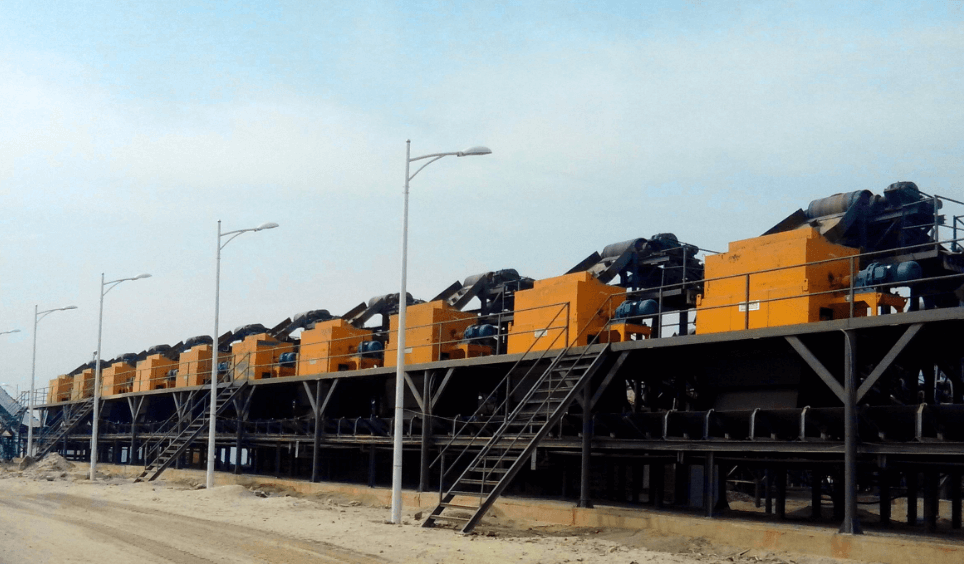
CTDG series permanent magnet dry magnetic separator is the most widely used for the dry throwing of ore with the maximum particle size of more than 20 mm.
Permanent magnet dry magnetic separator is widely used in metallurgical mines and other industries, can meet the needs of large, medium and small mines, used for magnetic separation plant crushed ore after the maximum particle size is not more than 500 mm material pre-concentration, throw away the mixed waste rock, restore geological grade, can save energy and reduce consumption, improve the processing capacity of the processing plant;
Used in stope, can recover magnetite from waste rock, improve the utilization rate of ore resources; Used to recover metal iron from steel slag; Used for garbage disposal and sorting useful metals.
Permanent magnet dry magnetic separator mainly using magnetic separation, ore evenly on the belt, at a constant speed to the upper part of the magnetic drum district, under the effect of magnetic force, the strong magnetic minerals adsorb on the surface magnetic roller belt, run to the drum bottom and out of the field, rely on gravity to concentrate slot, waste rock and weak magnetic minerals cannot be magnetic force to absorb and maintain its motion inertia, flat left to the front of the ore separator into tailings slot.
From the perspective of structure, the permanent magnet dry block magnetic separator mainly includes driving motor, elastic pillar pin coupling, driving reducer, cross slider coupling, magnetic roller assembly and magnetic system adjustment reducer and other parts.
Key points of structure technology
1. for the largest size in 400 ~ 125 mm thick crushed products dry because of the large ore particle size, coarse crushing after belt, bue to the belt department is expected to enter the drum separation area, with a thick layer of cast to achieve reasonable waste effect, reduce the tailings of magnetic iron content, this stage of the magnetic drum magnetic depth needs to have larger, to make a large ore particles to capture, the phase structure of the product technology main points: (1) drum diameter, the bigger the better, usually 1 400 mm or 500 mm.
(2) The width of the belt is as wide as possible. The maximum design width of the belt selected at present is 3 000 mm;
The belt is as long as possible in the straight section near the head of the drum, so that the material layer entering the sorting area is thinner.
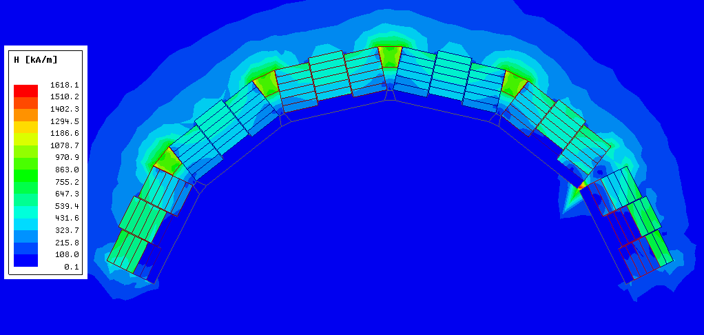
(3) For the larger magnetic penetration depth, taking the ore particles with the maximum sorting size of 300 ~ 400 mm as an example, the magnetic field intensity at the distance of 150 ~ 200 mm from the surface of the drum is usually greater than 64kA/m, as shown in Figure 1 and Table 1.
(4) The clearance between the plate and the drum is greater than 400 mm, and can be adjusted.
(5) The rotating speed of the drum can be adjusted, with the adjustment of the magnetic declamation Angle and the adjustment of the material separating device, so that the sorting index is optimal.
Fig. 1 Magnetic field cloud
Table 1 Magnetic field intensity KA /m
|
distance/mm |
0 |
50 |
100 |
150 |
200 |
250 |
|
Magnetic field intensity(kA/m) |
780.8 |
357.7 |
196.4 |
127.4 |
81.2 |
59.3 |
|
distance/mm |
300 |
350 |
400 |
450 |
500 |
|
|
Magnetic field intensity(kA/m) |
41.5 |
30.6 |
21.3 |
16.6 |
12.8 |
|
Table 1, the magnetic field intensity at 200 mm from the magnetic system surface is 81.2kA/m, and that at 400 mm from the magnetic system surface is 21.3kA/m.
(2)For the maximum particle size in 100 ~ 50 mm in the dry crushing products, due to the particle size becomes fine, the material layer thinning, design parameters and coarse crushing dry selection can be adjusted appropriately: ① the drum diameter is usually 1 000, 1 200, 1 400 mm.
② belt commonly used width 1 400, 1 600, 1 800, 2 000 mm;
The belt is as long as possible in the straight section near the head of the drum, so that the material layer entering the sorting area is thinner.
③For the larger magnetic penetration depth, taking the ore particles with the maximum sorting size of 100 mm as an example, the magnetic field intensity at the distance between 100 and 50 mm from the surface of the drum is usually greater than 64kA/m, as shown in Figure 2 and Table 2.
④The clearance between the distributing plate and the drum is greater than 100 mm, and can be adjusted.
⑤ The rotating speed of the drum can be adjusted, with the adjustment of the magnetic declamation Angle and the adjustment of the material separating device, so that the sorting index is optimal.
Fig. 2 Magnetic field cloud
Table 2 Magnetic field intensity KA /m
|
distance/mm |
0 |
10 |
20 |
30 |
40 |
50 |
60 |
70 |
80 |
90 |
100 |
|
Magnetic field intensity(kA/m) |
376 |
528 |
398 |
336 |
278 |
228 |
193 |
169 |
147 |
119 |
105 |
|
distance/mm |
110 |
120 |
130 |
140 |
150 |
160 |
170 |
180 |
190 |
200 |
|
|
Magnetic field intensity(kA/m) |
94.4 |
85.2 |
76.4 |
67.7 |
59 |
50.9 |
43.6 |
36.9 |
32.2 |
30.1 |
|
Table 2, the magnetic field intensity at 100 mm from the magnetic system surface is 105kA/m, and that at 200 mm from the magnetic system surface is 30.1kA/m.
(3) For the dry discarding of fine products with the maximum particle size of 25 ~ 5 mm, smaller drum diameter and smaller magnetic penetration depth can be selected in the design and selection, which will not be discussed here.
Post time: Feb-03-2021


